HOW THE ELECTROMAGNETIC SWITCH WORKS...

Electromagnetic switches trigger connection between the starter motor and the battery when control voltage is applied from the ignition or the appropriate controller in the car. Because of the high current involved during the start-up, all elements in this high-current circuit must be carefully designed and well maintained. Insufficient quality of any single element causes additional drop in the voltage supplied to the starter motor and thus reduces power generated by the starter.
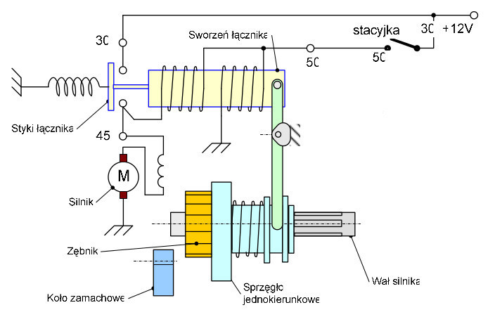
The switch contains two solid contacts and one moving contact. The moving contact is put in motion with a retractable core (so called plunger). In starters manufactured today, electromagnetic switches are frequently used in mechanical structures related to the so-called Bendix system.
How a starter electromagnetic switch works
- Initial phase
Ignition is switched off. The flywheel gear and the pinion are distant from one another. - Phase one
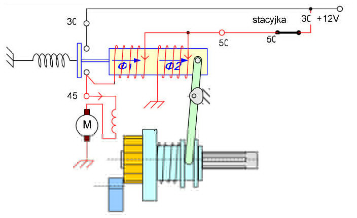
Once the ignition is switched on (engine start-up), voltage is supplied to clamp 50 of the switch. The flow of electric current through both coils generates two streams which sum up and retract the plunger. The coil with the larger-diameter wire and the motor switched on in series form a low resistance circuit. This results in high current, strong magnetic flux, and high retracting force. The plunger gets retracted and the pinion is moved towards the flywheel, and contacts 30 and 45 are closed. This phase lasts less than 1 second. - Phase two
Switch contacts are closed and the ignition is still switched on (in the engine start-up position). Once the switch contacts (30 and 45) close, the current in the coil with the wire of larger diameter stops since both ends of the coil have the same potential, i.e. +12V. The plunger remains retracted since the magnetic flux necessary for the plunger to remain in this position is much lower. The proper start-up of the starter motor occurs. - Phase three
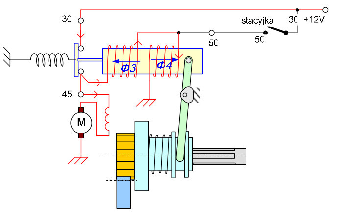
The switch contacts are closed – the ignition is switched off. The switch contacts (30 and 45) remain closed for a short time. Power supply to switch clamp 50 is cut off. Both coils are now connected in series and fed from the side of contact 45. Thus connected, the coils generate fluxes of opposite directions. Since the same current flows through both coils and the number of windings is comparable, the total flux is marginal and the plunger returns to the rest position. Contacts 30 and 45 are open.